2 To 1 Mux Block Diagram
Multiplexer (mux) Multiplexer mux logic stack Multiplexer (mux)
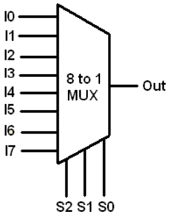
Verilog for Beginners: 8-to-1 Multiplexer
A multiplexer schematic structure, b truth table of the mux based on 2-to-1 mux using if-then-else statement in vhdl – buzztech Multiplexer 4x1 circuits mux multiplexers encoder inputs verilog code combinational udp theoretically 2n
Multiplexer (mux)
Design of 4×2 multiplexer using 2×1 mux in verilogMux logic multiplexer 2x1 verilog gates truth i2 technobyte 14+ multiplexer block diagram8x1 mux implement multiplexers logical functions.
Block diagram and circuit diagram of 3x1 muxMux multiplexer cascading multiplexing electricalfundablog Block diagram of the 2:1 mux ic.Construct 16-to-1 line multiplexer with two 8-to-1 line multiplexers.

Mux multiplexer verilog 4x2 2x1 muxes output
8x1 mux logic diagram : using 8 1 multiplexers to implement logicalMux vhdl using diagram block else statement then if 2x1 mux logic diagram : verilog code for 2:1 multiplexer (mux)Mux multiplexer cascading logic multiplexing bits.
Multiplexer (mux)Digital logic What is a multiplexer? operation, types and applicationsMux multiplexer cascading multiplexing electricalfundablog.
Multiplexer diagram block output verilog beginners figure
Schematic diagrams for (a) latch (b) selector in the mux.Logic multiplexer mux verilog 2x1 part15 ares gates Mux icMux logic schemas.
Verilog code for 2:1 multiplexer (mux)Mux multiplexer schematic structure inputs diagram considering Multiplexer mux logic inputs electrically4uVerilog for beginners: 8-to-1 multiplexer.

Mux multiplexer logic cascading application multiplexing
41 mux logic diagram : block diagram of 16 1 mux using four 4 1 mux16 mux multiplexer two construct line multiplexers diagram block if any constructed suitable assumptions dec2005 5m makes which same Mux 3x1 diagram circuitMux diagrams latch selector.
.


